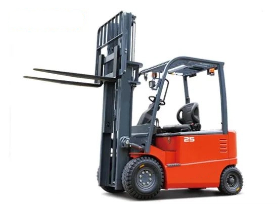
English Translation
The circuit diagram of an electric forklift typically includes a power supply circuit, a PWM generation circuit, a motor drive circuit, a discharge indication circuit, etc. The functions of each part are as follows:

- Power Supply Circuit: It generally adopts a regulated power supply circuit, which converts the voltage of the storage battery (e.g., 36V) to 12V to supply power to the control circuit, ensuring that the control circuit operates at a stable voltage.
- PWM Generation Circuit: With the TL494 pulse-width modulator as its core, it generates an oscillation frequency of approximately 12kHz through relevant resistors and capacitors, and outputs width-modulated pulses for controlling the motor speed.
- Motor Drive Circuit: Composed of components such as VDMOS transistors, it controls the permanent magnet DC brushed motor. The width-modulated pulses output by the TL494 drive the VDMOS transistors after amplification. The wider the low-level part of the width-modulated pulses, the longer the conduction time of the transistors, and the higher the motor speed. The freewheeling diode in the circuit can prevent the transistors from being broken down.
- Storage Battery Discharge Indication Circuit: It usually uses an LM324 or LM339 chip. Through multiple comparators, it controls the on/off state of the LED lights according to changes in the storage battery voltage, thereby indicating the battery power status.
- Storage Battery Over-Discharge Protection Circuit: When the storage battery voltage is lower than the set value (e.g., 31.5V), the relevant chip outputs a low level, turning on the triode and forcing the internal width-modulated pulse output transistor of the TL494 to cut off. As a result, the motor stops running, preventing the storage battery from being damaged due to over-discharge.
- Motor Over-Current Protection Circuit: When the motor current exceeds the set value, the voltage across the current sampling resistor exceeds the threshold, causing the internal operational amplifier of the TL494 to output a high level. This stops the motor from running and protects the motor from damage caused by excessive current.
- Brake Protection Circuit: When the brake is applied, the relevant switch is turned on, applying voltage to the dead-time control terminal of the TL494. This forces the internal width-modulated pulse output transistor to cut off, making the motor stop running quickly and realizing brake protection.
In addition, the circuit diagram of an electric forklift may also include components such as a key switch and a limit switch. The key switch is used to turn on the power supply of the entire control system and plays a role in safety protection; the limit switch can control the stroke of the forklift's movement mechanism, such as controlling the limit positions of the lifting rod when it rises or falls.


